The OC1 is a four-segment DCC block occupancy detector. It is completely powered from DCC, and provides four optically-isolated outputs with a common ground. The advanced microcontroller design allows for previously unavailable occupancy detection features, including compensating for the unoccupied current level and easy sensitivity setting in small calibrated steps. A single axle with a 10 kΩ resistor between the wheels can be reliably detected.
The OC1 is available on line from these resellers:
Click here for more information on Olin's Depot resellers.
The OC1 can be connected to up to four track segments at a time as shown in this diagram:
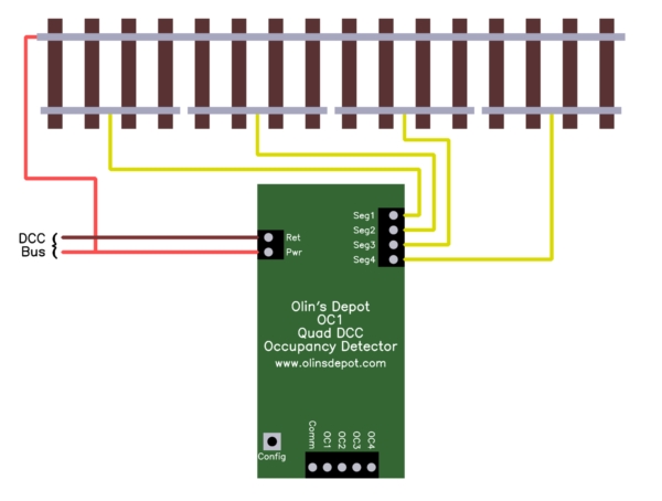
DCC power does not have a polarity, so can be hooked up either way. The DCC line connected to the Pwr terminal must also be connected to the common rail for all track segments covered by the OC1 unit. The other DCC line must be connected to the Ret terminal. The Seg1 thru Seg4 terminals are connected to the other individual rails for each track segment. Note that this side of the rail must be separate for each track segment. Use insulating spacers or gaps as necessary.
When sufficient current is detected accross track segment 1 (Seg1 terminal), the OC1 output will be asserted. Likewise, current in segment 2 will assert the OC2 output, etc.
The five output terminals (Comm, OC1, OC2, OC3, OC4) are completely floating relative to the DCC power.
In electronics jargon, the OC1-OC4 signals are NPN open-collector outputs with Comm being the common emitters. In practical terms, you can think of there being four switches. Each OC1-OC4 terminal is connected to one end of one switch, and the other ends of all four switches are connected to Comm. When occupancy for a segment is detected, the switch is turned on, otherwise it is left off. In essence, each OCx output is shorted to Comm when occupancy is detected, otherwise not.
Unlike normal mechanical switches, these solid-state switches can only handle voltage in one direction. Comm must always be at the same or lower voltage than any of the OCx outputs. Normally Comm is connected to ground. The OCx outputs then either connect their lines to ground or effectively stay disconnected.
The maximum current thru each switch must also not be exceeded. These switches can handle up to 25 mA (milliamps). That is sufficient to light most ordinary LEDs, which are usually rated for 20 mA maximum.
Here is a example connecting LEDs so that they light when a track segment is occupied. This assumes separate 5 volt power is available:
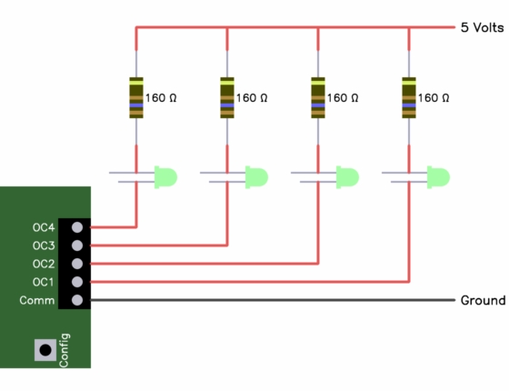
With a 5 volt supply, you should not use resistors smaller than 160 Ω since that results in nearly the maximum of 20 mA the LEDs can handle. Most LEDs are still quite bright with 10 mA current. If that is sufficient, use 270 Ω resistors.
Most LEDs that look like what is shown in this diagram have two leads of different length, with the longer one being the positive connection. However, this is not a universal rule, and you should try flipping the LED around if it does not light. The fancy electronics name for the positive lead (connected to the resistor in the diagram) is the "anode", and the other lead the "cathode". If the LEDs are built into other equipment, like signal lights, then the documentation may only describe them with those terms.
Various settings can be selected via the single user button labeled Config. Different button actions are distinguished by different sequences of short and long presses of the momentary button. A short button action is called a "click", which is the button held down for less than 1/3 second. A long action is called a "press", which is the button held down for more than 1/3 second. For successive button actions to be part of a sequence, the gap between actions must not exceed 1/2 second.
All settings persist until deliberately changed, whether power is shut off or not.
The valid button sequences are:
Saves the immediate measured current values as the zero current level. For occupancy to be detected, the measured current must exceed this level by the trigger threshold. The zero current level is measured and saved for each track segment separately.
Capacitive coupling and leakage, and therefore the apparent current drawn by a unoccupied track segment, can change as wires are moved around. This zero level setting should be performed after all the DCC connections have been made to the OC1, all wires run and mounted for the track segments being tested, and the OC1 has been mounted. If the wiring between the OC1 and the track segments changes or is moved, the zero level should be re-set.
Make sure everything is removed from the track segments being monitored before setting the zero current level. The zero current level is only intended to compensate for capacitive coupling and leakage, up to a few milliamps. It is not intended to compensate for other equipment being powered by the DCC of the covered track segments, like switches, reversers, etc. These can draw a unpredictable amount of current, and their current level can be higher than the zero current the OC1 can detect and save in its memory.
This action is confirmed by all four lights flashing together for a short time.
Turns off the occupancy hold time. The occupancy outputs will indicate the immediately measured conditions. This mode can be useful for setting up and debugging because the result of actions can be seen quickly.
This action is confirmed by the four lights showing in sequence right to left.
Turns occupancy hold on. Each occupancy output will continue to be asserted for two seconds after any time occupancy is detected.
This is probably the mode you want to use for normal operation. The wheels of rolling stock don't always make good electrical contact with the track due to dirt and bouncing. This setting prevents small interruptions in current from causing the output to signal no occupancy. Also in many layouts, the signals driven by occupancy are supposed to persist for a few seconds after a segment becomes unoccupied.
Usually the only reason not to enable the two second occupancy hold during normal operation is if the occupancy signals are driving other equipment that also implements a hold, or driving computer inputs where the software performs its own hold logic.
This action is confirmed by the four lights showing in sequence left to right.
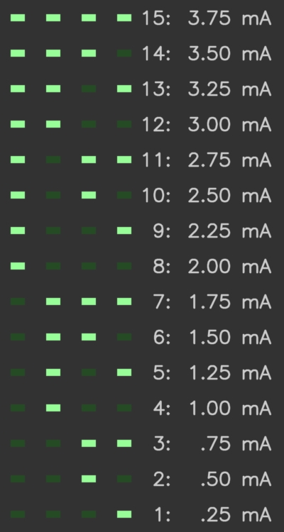
Lowers the threshold for detecting occupancy. Occupancy is determined by the measured current minus the calibrated zero level (see press above) exceeding the threshold. This threshold can be adjusted from 1 to 15, which is in units of 1/4 milliamp. The factory default is 7 (1 3/4 milliamps).
Perform this operation if you find occupancy is not being detected when it should be. Whenever you are getting unexpected readings, always make sure that the zero level is properly calibrated first. See the press action earlier in this section.
Keep in mind that occupancy is detected by rolling stock drawing current. Unpowered cars usually don't draw any current, so can't be detected without deliberate resistors connected between opposite wheels. The OC1 is sensitive enough so that only 10 kΩ should be needed. A 10 kΩ resistor draws such a tiny amount of the power that many axles can be equipped with these resistors without significant effect on the total power budget. For example with 22 volt DCC, which is the maximum allowed by the DCC standard, a 10 kΩ resistor draws only 2.2 mA. 20 axles with 10 kΩ resistors would then draw only 44 mA.
This action is confirmed by displaying the new 1-15 threshold setting in binary on the lights for one second. The display patterns, their binary values, and the corresponding detection thresholds in milliamps are:
Like click-press (above), except that the occupancy detection threshold is raised instead of lowered. Perform this action if you find the OC1 detecting occupancy when it should not. Whenever you are getting unexpected readings, always make sure that the zero level is properly calibrated first. See the press action earlier in this section.
The board has four LEDs labeled OC1-OC4. During normal operation, these provide a visual indication of when occupancy is being signalled for their associated segments. Special displays are shown on power up and after button actions. Note that the outputs are asserted whenever the LEDs are lit. This means occupied signals are sent after power up and after button actions, even though the associated track segments may not be occupied at that time. The Button section (above) describes what is displayed to confirm each button action.
On powerup, the lights display patterns to allow visually verifying their operation, and to show some of the current settings. All four lights are flashed together briefly after powerup.
After the initial flash, the occupancy current threshold is shown for one second. This is the same display as follows a increment or decrement of the threshold. See the click-press button action for details.
After the occupancy detect threshold, the lights indicate whether occupancy hold is on or off. The four lights are blinked in sequence, with left to right indicating occupancy hold on, and right to left indicating off. This is deliberatey the same display as after the button actions that set the occupancy hold on or off.